Friday, December 26, 2014

Python web application deployment, my setup


There are many options to deploy Python web applications or WSGI-compliant applications in general. Using Apache or Nginx is a popular choice.

Here I will use the following software, which happens to be 100 % Python:

  • Flask, a Python framework for web applications, but other WSGI-compliant applications should work just as well.
  • Tornado, a scalable non-blocking web server written in Python
  • Supervisor, a system for controlling process state similar to Linux's init. Configuring a standalone daemon is another option, although less flexible.

Step 1

Make sure your Flask application is enclosed in a function.
It's basically something like this:

def create_app(any_parameters_you_like):
    app = Flask(__name__)
    app.config['SERVER_NAME'] = 'johndoe.com:1234'
    return app

Outside of any method, you can write something such as:

app = create_app()

There are several things to note here:
  • You need to specify the URL and port that will be used to access the web application.
  • By default, the built-in server started on the last line only listens for local connections, "0.0.0.0" will make your application accessible from the outside (LAN and any other network).

Step 2

Create a file my_tornado.py anywhere you like, for instance in the same directory than the app. Here we suppose the create_app() function is in a file named my_module.py.

The content of this file for servers requiring SSL connections is as following


#!/usr/bin/env python
import sys 
import os
sys.path.insert(0, os.path.dirname(__file__))
sys.path.insert(1, '/any/other/directory/to/add/to/your/path')

from tornado.wsgi import WSGIContainer
from tornado.httpserver import HTTPServer
from tornado.ioloop import IOLoop
from tornado.web import FallbackHandler, RequestHandler, Application
import tornado.web


import my_module
app = my_module.create_app()

application = Application([
    (r"/my_app/.*", FallbackHandler, dict(fallback=WSGIContainer(app))),
    ])  

http_server = HTTPServer(application, ssl_options = { 
    "certfile": "/etc/ssl/certs/my_server.crt",
    "keyfile": "/etc/ssl/certs/private/my_server.key",
})
http_server.listen(1234)

print 'Ready.'

IOLoop.instance().start()


As explained, in this example SSL is activated. Also a non standard port (5000) is used. You can change the options and run in insecure mode. For SSL you need to roll your own certificates.

Launch the Python file. The app should be running fine.
Because I was launching this on a Raspberry Pi it took several seconds to start. Thanks to the "Ready" message you will know when the server has completely started.
See if "/yoursite" is accessible.

Step 4

Make it start at boot using init.d, xinetd or other techniques. Here I am using Supervisor.
You can optionally enable the web interface in the config /etc/supervisord.conf which will look like this:


Add a new section to the file:

[program:my_app]
command = /home/pi/my_webapp/my_tornado.py
startsecs=10
stopsignal=INT
user=pi

Change the appropriate settings if necessary. Note stopsignal is the signal sent to the process so it stops itself, it's the first argument of "kill". Sending SIGINT has the same effect as pressing Ctrl+C after Tornado has been started.
startsecs is a hint for Tornado : the service is considered running if the process is still up after 10 seconds.
As explained you can also use a standalone daemon, but Supervisor is more flexible and doesn't need any configuration and fiddling with boilerplate code.

Ensure Supervisord starts with the system.
UPDATE:  I had a problem recently because one of the services declared with supervisord required another service (started with a regular init.d script) to work. The workaround is to start supervisord after everything elseby appending "$all" at the end of #Required-Start in the init.d script as described at the bottom of this page.

That's it, we're done!

Saturday, December 13, 2014

Tutorial: Linux firewall and IPTV (e.g. Swisscom TV)


Swisscom TV like any IPTV network really, relies on two technologies to deliver its content to its users:
  • Multicast adressing
  • IGMPv3
  • (IGMP snooping)
 I probably don't need to explain what Multicast is. You should only know that this is what has been causing network administrators many headaches!
Netflix and YouTube don't use Multicast but Unicast instead, only YOU are receiving a particular stream. This is the difference between Video-on-Demand and IPTV.
Speaking of which, when you are watching shows from the past days on Swisscom TV, it's actually sending Unicast packets.

IGMP allows clients (your TV or Set Top Box) to register itself for multicast traffic. This is basically the protocol that is used to select the TV channel, so that the STB can receive it.

IGMP snooping prevents your home network (possibly even the Wi-Fi network) to be flooded by the video stream packets even though only one TV
 needs them. This is a Level 2 technology implemented in switches.
We won't deal with IGMP snooping here, only with the first two.

This tutorial is based on Debian 7.7 but can work anywhere where IGMPProxy can run.
  1. Download IGMPProxy, compile and install it.
  2. Swisscom seems to use the following subnets:

    213.3.72.0/24
    195.186.0.0/16

    We'll add them to the igmpproxy configuration in /usr/local/etc/igmpproxy.conf. I have it configured like this:

    quickleave

    phyint eth0 upstream  ratelimit 0  threshold 1
            altnet 192.168.1.0/24 # see below
            altnet 213.3.72.0/24
            altnet 224.0.0.0/4
            altnet 195.186.0.0/16

    phyint eth1 downstream  ratelimit 0  threshold 1
            altnet 172.16.123.128/29 # see below

    phyint lo disabled


    My configuration (adapt to your needs):
    eth0 is the WAN interface
    eth1 is the LAN interface

    192.168
    .1.0/24 is the subnet between the Swisscom modem and the firewall
    172.16.123.128/29 is the subnet I dedicated to STB.
    224.0.0.0/4 identifies multicast addresses. It goes from 224 to 240, hence the /4 network mask.
    See the documentation for the meaning of quickleave.
  3. Configure the firewall to let said subnets in the INPUT chain. Allow FORWARDing between both interfaces.
    (These instructions are vague on purpose. If you are running a firewall you obviously know your policies and rules better than anyone!
    If you want to be precise you will have to allow for the IGMP protocol with the parameter -p igmp of IPTables for instance).
  4. Launch igmpproxy in debug mode, as root:
    igmpproxy -d -v /usr/local/etc/igmpproxy.conf

    See if you can watch TV. Look at the addresses. Try to add them to your configuration, relaunch the proxy and see if it works.
  5. Schedule igmpproxy to start at boot.
    You can use this script and follow the instructions at the bottom of the page. (Discard the explanations in Russian in-between ;-))
  6. Happy TV watching!


    Here's what the traffic looks like while I've been playing with this:
    (This is with pnp4nagios and the stat_net plugin, which is based on /proc/net/dev.)

I am actually quite surprised by this. It seems to need only 3 MBit/s for one TV (and not recording a second channel). I would have expected from 2 to 3 times more bandwidth usage.
I tried nload just to make sure:

Same observation!
(Possibly because /sys/class/net/eth0/statistics/rx_bytes which nload uses, is filled by the same kernel module as /proc/net/dev, in which case this should be accurate as these are the actual frames read by the Linux kernel.)


If you are getting continuous messages in your syslog:

I tried everything. I can either stop the messages or watch TV. For some reason, the STB sends "upstream" IGMP packets. It's very strange and doesn't make much sense. The IGMP proxy doesn't "proxies" them and the TV runs smoothly.
I figured I could safely ignore these. You should also note that IGMPProxy is a very young project (version 0.1).

I added this near the beginning of /etc/rsyslog.conf::msg, contains, "The source address 172.16.123." ~

and restarted the rsyslog daemon. The messages are finally gone. Another solution is to use another file for IGMPProxy logs.


Keywords: linux, unix, firewall, shorewall, bsd, iptables, netfilter, bluewin tv, swisscom, iptv, multicast, 

Getting instant notifications on your smartphone or tablet from Nagios


If you are a network administrator or manage a production system of some sort, you might be interested to be notified as soon as possible in the event of problems.

Nagios is a great tool to watch your hosts and services and even though it's kind of 1990-ish it still does a very good job and stays the most used tool for this task.

It can natively send e-mails. That's great, but I don't know about you, I get more than 40 e-mails a day, and even with SaneBox and other tricks it's easy to miss e-mails and it can literally take days until I notice one that was more important than the others.

Pushover provides instant notifications on handheld devices such as Android, iPhone, and iPad using "push" technology (instead of polling).
It has many advantages:

  • It uses a REST API, meaning you can use it in all scenarios you ever dreamt of.
  • They provide clients for smartphones, tablets and they even support OS X Growl notifications.
  • It's inexpensive at only $5 USD.
  • You don't need to run or install any software on your servers.

Here is a tutorial on how to use it with Nagios, based on Debian 7.7 stable, as of December 2014:

  1. Create an account on Pushover. Mark down your personal key.
  2. Create an application. Mark down the application key.
    I named mine "Nagios" but you can choose anything you like.
  3. Set up your account on one of your devices.
  4. Download Jedda Wignall's script in your plugins directory with your root account:
    wget -O /usr/lib/nagios/plugins/notify_by_pushover.sh https://raw.githubusercontent.com/jedda/OSX-Monitoring-Tools/master/notify_by_pushover.sh
  5. Make it executable:
    chmod +x /usr/lib/nagios/plugins/notify_by_pushover.sh
  6. Create a Nagios command to run it. I like to have a /etc/nagios3/conf.d/custom_handlers.cfg file, but you can name it with any name you want as long as it is in that directory. Copy the following coutent to it:

    define command {
        command_name        handler_pushover
         command_line       $USER1$/notify_by_pushover.sh -u $ARG1$ -a $ARG2$ -t "$ARG3$" -m "$ARG4$"
    }


    $USER$1 stands for /usr/lib/nagios/plugins and $ARGn$ will be replaced with arguments set after the command-name following "!" in the next step.
  7. If you want every host to report a failure (and supposing you used the template everywhere), modify /etc/nagios3/conf.d/generic-host_nagios2.cfg, and add the following line anywhere inside the host definition:

    event_handler                   handler_pushover!PERSONAL_KEY!APP_KEY!Nagios!$HOSTNAME$ : $HOSTSTATE$
    Replace the personal key and the application keys with the ones obtained in step 1 and 2.

    "Nagios" here is the title that will appear in the notification, it doesn't need to match the application name and it can include spaces.
  8. The last parameter of the command (everything after the last "!") is the message. Here I simply chose to show the hostname and the state. The variables enclosed in dollar signs can be found in the Nagios manual.
  9. If you want every service to report a failure (and supposing you used the template everywhere), modify /etc/nagios3/conf.d/generic-service_nagios2.cfg, and add the following line anywhere inside the service definition:

    event_handler                   handler_pushover!up4evfJ7bkP43M5mLvGZ24Gp1aoM14!a6fLnAFT2rNMCXeEeogbghbLbV1o9m!Nagios!$HOSTNAME$ / $SERVICEDESC$ ($SERVICESTATE$) : $SERVICEOUTPUT$

    This will print the status of the service as well as the line shown in the web interface.
    You can include modify "Nagios" (title of the notification) and everything after the last ("!") with macros from the Nagios manual.
  10. Reload Nagios:
    service nagios3 reload
  11. Provoke a "warning" or "critical" message in Nagios. You should receive a notification as soon as the problem is discovered by Nagios.
Life is great!

Now, there may be better ways to do this. You should probably use the notification mechanism from Nagios instead. The handler is supposed to "handle" the problem, not report it. As a result I had to put retry_interval 120 in some of my service definitions to avoid getting the same message again and again.

Tell me what you think and how it worked out for you!

Saturday, November 15, 2014

Tutorial: Complement your Android app with a smart watch interface

The LG G Watch R just came in the mail yesterday, and already felt the urge to "hack" on it!


It's a round watch with a touch screen and a sporty look. I love it so far!

About This Tutorial

In this tutorial we will see how you can extend an existing Android application for handheld/smartphone by providing a dedicated interface for an Android Wear device
If you are starting from scratch the development website from Google might be a better resource.
Unfortunately it lacks a lot of information, as it never gives you the generated code you need if you are adapting an existing app.

I already have an app for the phone that sends an HTTP request to a web service which eventually opens the garage at my house. I want to be able to trigger this action from the watch.

So we'll have this:

            Bluetooth                WiFi/HTTP
[watch]   ------------>  [phone]  -------------->  [web service]


Resources

The Google Developers website contains the info you need regarding other uses of the APIs, the documentation of the layouts and so on. Make sure to check it out.

Tools

Make sure you have all these tools:
  • An Android Wear device. The emulator just isn't enough I think, but YMMV.
  • An Android phone
  • The Android Wear app on your phone
  • Recent build tools and SDK. API 20 features Android 4.4W. W stands for "Wear". The LG G Watch R runs 4.4W2.
  • Gradle 2.1 or later. I unzipped the thing somewhere and added the "bin" folder in my PATH.
    Don't use the wrapper that comes with your IDE or the outdated version from your package manager on Linux.
  • A terminal emulator. I use "Console 2" on Windows
You can use Android Studio or Eclipse with the ADT and Gradle plugins. Actually you don't even need an IDE for this tutorial. I will show you how to use ADB and Gradle from the command-line because it requires no configuration, but you should be able to build and deploy the project from your favourite IDE.

I did all this on Ubuntu Linux 14.04.3 LTS, but it should work just the same on Windows and OS X.
If you've got a Samsung phone, you will need to download the Windows drivers from the Samsung website.

Step 1: Check your installation

Fire up the command line and make sure  everything's working properly.

adb devices should list your phone.
gradle should say "Welcome to Gradle 2.1."

If they don't, make sure they are in your path.

Step 2: Enable debugging on your watch

By the way, when the folks at Google use the word "debugging" they really mean "Allow ADB to communicate with an Android device".
ADB (Android Debug Bridge) is also what you use for reading logs, installing, uninstalling, and starting apps from your computer.

Here's how you communicate with a watch that doesn't have a USB connector:

            Bluetooth               USB
[watch]   ------------>  [phone]  ------->  [computer]

The Android Wear app on the phone runs a TCP server that allows you to connect to the watch from your computer as if the watch was connected with a USB cable.

Follow these steps to setup the whole thing.

Note the TCP/IP connection over Bluetooth and USB is very unstable.

In the next steps we will install the app on the "wearable". You will see more often than not, the watch is no longer "online" or the installation won't work because of an error.
In that case here's my advice to restart a broken connection:

1. adb kill-server
2. adb forward tcp:4444 localabstract:/adb-hub
3. adb connect localhost:4444
4. wait 2 seconds (I know some people will automate this in a script ;-))
5. adb devices (make sure the wearable is listed)

Step 3: Use Gradle in your project

I tried using the legacy build system of IntellIJ IDEA for Android projects but I realized it's a big waste of time and we will all need to use Gradle eventually for lots of reason, the main one being that it is the standard imposed by Google.
They still support non-gradle builds for now, but it probably won't last...

So make sure your project already compiles with Gradle.
If you are planning to write a smartphone AND wear application as we are going to do, you can't just migrate to Gradle by keeping your existing directory structure (which is explained here).

You need to use the standard directory structure for a Gradle "multi-project". Remember Gradle believes in "convention over configuration", so your build files are very short (unlike Maven) because you will be using the default configuration.

Step 4 : Main Project structure

Remember my "Garage Opener" application? Here's the new structure:


You can see this project contains two modules: phone and wear.
They contain the code and resources respectively for the smartphone and the watch.
Note the smartphone APK will package the watch APK so that when users install your phone app the watch app is automatically installed on the watch.
This is not my choice, it's what Google decided. But when developing we will be able to install the watch APK directly on the watch. Your only way to uninstall an app from the watch is by using ADB. You can't do it from the watch or the phone.

The main project is a "multi-project", that's why it doesn't contain a build file (build.gradle).
Instead there only is one file you need: settings.gradle.

Here's the content of the settings.gradle file:

include 'phone', 'wear'

We could have had two completely different projects and run gradle from there. Each builds his APK file and runs on the appropriate device. That multiproject thing is needed only because the phone app includes the wear APK.
As a matter of fact, you should not have dependencies between modules!

Step 5 : Handheld module structure

Here's the content of the phone module:


It contains the Java source code for the activities as well as the resources (images, layouts, translations) as in any project.
It also contains the AndroidManifest.xml file (in the src/main folder).
Mine is like this:
That is the actual content of my file. I only put it to be exhaustive. You should actually use the one you already have. I will explain later why the service is needed.

One important thing though: the package name needs to be the same in both AndroidManifest.xml files. (We will have one for the watch as well.)

This is the content of the build.gradle file:


The things that matter here:
  • You need to compile with at least SDK 20 that includes Android 4.4W (Wear edition).
  • Use the latest version of the build tools.
    When working in a team I advise all people to use the same version.
  • The applicationId must be the same in both modules.
  • The phone doesn't need to run the latest flavour of Android. For instance here the phone app will run from Android 4.2 (API 17) to Android 5.0 (API 21).
  • Uncomment the middle section to sign the release APK. This APK is generated with the "assembleRelease" task from Gradle, as we will see later.
    NOTE: You should not put the passwords of the keystore and the key (and probably not even the keystore itself) on your VCS. It is possible to have this information in another (untracked) file, but for the sake of simplicity I didn't do it here. (because to be honest, it's painfully hard to do and not well-integrated yet. I hope they will make it a built-in option some day.)
  • Use repositories instead of JARs copied in the libs/ folder whenever possible.
    (Just so you know, in this project there are no JARs.)
    If you are in a team you probably want to have your own repository to share binaries other developers will use in other projects.
  • My phone app communicates with the wear app (that doesn't need to be the case), that's why there is a dependency to Play Services Wearable. You don't necessarily need that.
  • The weapApp tells Gradle to package the wear app inside the phone app.
  • Note the semi-colon.

Step 6 : Wear module structure

And here's the content of the wear module:


There's the activity and the resources that will be displayed on the watch. Note it's probably silly to put the folders for high resolution drawables.

Again, the AndroidManifest.xml:


To be honest I'm not so sure about the parameters of the .WearActivity, but they worked.
You can see I also included an activity that's not mine. We will start it from our application, that's why it's needed. It's actually the one displaying a green circle to show an action was successful.

The meta-data thing is needed because we will communicate with the phone through the Google Services APIs (don't ask me why).
I am now noticing no permissions are required. I do know you can have uses-feature though, for instance if your app relies on the pedometer or other hardware bits the watch might or might not have.

As I said earlier, the package name needs to be the same in both modules.

And here's the content of the build.gradle file:

It should look the same as the phone app for the most part, except for:

  • The minSdkVersion must be at least 20, because that's the API release number for Android 4.4W (Wear edition).
  • The targetSdkVersion doesn't need to be the same, must be equal or greater than minSdkVersion. That goes for all Android applications for all devices.
  • versionCode and versionName is not the version of a framework but the version numbers for your application.
  • There is a dependency to android.support:wearable that you must include. The other one is only needed if you intend to communicate with the phone from the watch (or the other way around).

Step 7 : Watch app layout

Let's start with what the application will look like on the watch:


Incredibly simple, right? It must be. Don't try to do too much with a wear app. Be more minimalist than the most minimalist person in the world.As a matter of fact Google has a whole page of guidelines to design wear apps.I prefer round watches, but keep in mind this is Android. There will be plenty of different screens and resolutions and you should design for as much hardware variants as you can.This guide explains you how to design for round and rectangular screens.There will be three files:
  • activity_wear.xml
  • rect_activity_wear.xml
  • round_activity_wear.xml
We never reference the last two from the Java code. The WatchViewStub in the activity_wear.xml layout will choose the right one. That's why it's called a "stub".Here's activity_wear.xml:

If your IDE is shouting at you right now, it's because you need to "Sync" the project (in Android Studio) because it has to read the build.gradle file to know how the android.support.wearable package is defined. Note Android Studio / IntelliJ IDEA will propose you to solve the problem by adding the appropriate JAR to your classpath. BAD IDEA! (No pun intended.) The idea won't complain anymore but the project will not compile with Gradle. I had to do both.

Now, about the layou tfile, you can see the stub takes all the space available (because of the match_parent value).
The tools namespace is only for Android Studio so the Preview is displayed correctly. You don't need the related attributes.
What you absolutely need though is the app: attributes. This tells the stub where to find the actual layout files.

round_activity_wear.xml (and rect_activity_wear.xml as a matter of fact, but I couldn't really try it on a real watch):

This layout is really not something to take as an inspiration. I show it to you for exhaustivity but I implore you not to use all these hardcoded widths and heights.
It's not even centered vertically (although if you read the code it should, right?!)
I can't give you the images for the arrows for copyright reasons. Just know these are transparent 96x96 PNG files.

The BoxInsetLayout allows you to display something square on a round screen. You can use this trick if you are lazy and don't want to design a specific layout for round screens.

Step 8 : WearActivity / Sending a message to the phone

That's the activity that will run on the watch. Yes, the OS and APIs are the same on all Android devices, for most of them. Watches will have activities. As a matter of fact, watches are even able to run some phone apps unmodified (but the interface won't be really practical or even useable).

Here I will directly include the code to communicate with the phone:


Some of this code is based on the Google tutorial, but unfortunately the folks at Google forgot to include vital pieces of code and I had to figure out myself how to use their libraries.

Let me explain you this code.

In the onCreate() method, we "inflate" the WatchViewStub and attach a Listener to it. This makes it display the round or the rectangular layout. When that layout is inflated, we can do what we would usually do in the onCreate() method. We set the OnClickListeners of the buttons in the OnLayoutInflatedListener.

The sendCmd(String) method will send some data (here a String but it could have been any sequence of bytes) to the phone app.
As it runs network code, we need to enclose that code in an AsyncTask (as in any Android app).

It uses Google's MessageAPI to communicate with the phone. In order to use this API, we need to connect to the Play Services Infrastructure. You can find the code in the getNodes() method.
The getNodes() method lists the Android devices you have associated with your Google account. You should probably filter them to select only your phone I think, but in my case it worked this way.

In onDestroy() we disconnect from the Play Services.

We need to provide an "Activity Path" that acts like a URI. An optional payload (which we use here) can be sent along with the message. The MessageApi sends data asynchronously, but we use the .await() method to make it synchronous again.
When the message could be sent successfully, we start the ConfirmationActivity that all apps can invoke. It's not one of our activities. The extra message is the text that appears below the green OK image. You could print "Message Sent" instead.
As a matter of fact you should rather put a translation in the strings.xml files, and reference it with
getString(R.string.my_text).

Speaking of things you "should rather do", the best practice is to put a Confirmation Timer as explained here.
I wanted to do it but again, the explanations from Google are lacking and it didn't work.

Step 9 : Receiving a message on the phone

Maybe now you should be able to figure out why we had dependencies to Play Services and what were the service definition in the AndroidManifest.xml in the phone module was for.
Let's see that again:


The phone will receive the message using a Service.
We have to create a service. Here I named it "AndroidWearMessageListenerService":


First thing you should see is that the "Activity Path" has to match in the wear and the phone apps.
To my understanding, you can choose it freely.

Remember our message came along with some optional data that can be any sequence of bytes. Here I sent an ASCII String. That's why we need the constructor from String() that, just so you know, must never be used like this: new String("some string").
I purposefully don't handle NullPointerExceptions. 

Step 10 : Compile the project

Go to your main project folder (the one with the settings.gradle file) and run:

gradle installRelease

This will compile the project, package it and install it on the phone and the watch.
(Note you might have to try installDebug if you didn't configure the release config in Gradle build files).

Unfortunately, Gradle could not install it on the watch because it takes a bit of time and Gradle ignores the Timeout that you have set in DDMS. See this post.

Workaround:

adb -e install -r wear/build/outputs/apk/wear-release.apk

This takes about 40 seconds (!) on my setup.
If you run an emulator at the same time you need to provided the host and port (localhost:4444) as well, as explained in the Google tutorial.
If you will be doing this, then I advise to run the assembleRelease task to save a little time when you don't need to install the app on the phone because it didn't change.

To install the phone app you can use this:

adb -s 123456e1 install -r phone/build/outputs/apk/phone-release.apk

where 123456e1 is the identifier you can find with adb devices.

Step 11 : Enjoy!

If everything went fine, you now have a nice app to show to your friends and be prepared to do the coolest things with your watch!

Step 12 : Improve and share

Improve the app by adding the Confirmation Timer and tell use how you managed to do it.
Share any other tricks you found, even if you think everybody knows them.

You might also want to handle errors (could not connect to phone, could not connect to web service, web service returned an error) and so on...

Saturday, November 8, 2014

Open your garage door with Raspberry Pi and Android


This project involves developing an Android application, a web client and a web service to open and close an electrical garage door. The Raspberry Pi version B and a USB relay board will be used to make the connection between the client devices and the garage door motor.

For now I won't include any code, but if you are interested I can update the article to make it available.
That's not that I don't want to, but for me it's a very different thing to write code for a personal fun project and publish a polished source code example people will try to understand, use and extend.
Re-writing the code in this intent, documenting it properly (with Doxygen or Sphinx), making it work in several environments and explaining it takes a lot of time.

But if you are interested in the code of a particular component, feel free to ask!

I'll provide pictures and a video demonstration at the end of the article.

Context

My garage door was installed in 1997.
It can be opened and closed with three devices :
  • a push button inside,
  • a keypad outside,
  • a 435 MHz remote control.
The first two are fine, but the third option had many issues :
  • Often times, you would press the button and nothing happened, or only on the 20th attempt.
  • It used a battery such as those you would find for wrist watches, except it was not one you could easily find.
  • I had only two remotes and I needed more.
Also, sometimes I was away from home and would let a package or the key of the house in the garage. I would give the code of the keypad to a friend that would come over to get it.
I trust them but I would rather not give them the code. This solution is still better than hiding the key under the mat, but there had to be a better option.

Requirements

The features I wanted for the new remote control:
  • Work on first attempt
  • Fast, like pressing the physical button inside the garage.
  • Be able to open the door for friends when I am away
  • Secure
  • Access Control
  • No additional device. Everyone that will be using it has a smartphone. let's use them.
    (Of course it would work over Wi-Fi only, but with a data plan they could open the door outside of the Wi-Fi range.)


Solution

There are many solutions to solve these problems, and the one I chose is totally overkill. I know that, but I had fun doing it and it has many features you wouldn't find with a simpler system.

So here is my solution.
For the clients:
  • Android application
  • Mini web application. Works everywhere, including PCs, iPhones, ...
For the server:
  • Raspberry Pi
  • RESTful Web Service over HTTPS
  • HTTP Basic Authentication
  • Identification using Google account and/or phone number
  • Relay(s) allowing the Rasperry Pi to open and close the garage door


Overview


So, this system will use the Internet over a secure HTTP link to connect the Raspberry Pi with the clients.

The Raspberry Pi will run a web application that will verify the client is allowed to make a request, and if so will transmit a command to some middleware.

The middleware is made of several little software components that converts the command to bytes sent to the USB Relay Board over USB.

Between this "command" and asking the relay board to close the circuit on the right side, there is a software component that I call "GarageDoorController" (not shown in this schematic).
It is responsible to manage access to the relay board. As I know it takes 20 seconds for the garage door to open or close, that software component will prevent concurrent commands. Even a client might press the button on the Android app twice, and that would cause the garage door to stop at the second press, leaving it half-opened. (Although you might actually want that behavior.)

The USB Relay Board consists of several relays able to handle high voltage (230 V) and high current (up to 10 A).
One pin of the relay is used to make or break the contact between the two other pins. These two other pins are connected to pins on the garage door motor board. 
The particular device motor board I have can distinguish between opening and closing the garage door, but your device might not. It also has pins to lock the door and prevent anyone closing or opening it, and pins to switch on and off the halogen light mounted on it, plus a few other things.

At the very end, the garage door motor is powered on, and the garage door opens or closes.

NOTE : I already said it, but this is MY solution. There are many others that may be more efficient or more suitable for your needs.
Depending on your skills you might want to wire the GPIO pins of the Rasperry Pi to relays on a custom-made board.
You may also be paranoïd and think SSL is not safe, or you might not have an Internet connection in your garage and use Bluetooth (or make your Raspberry Pi act as a WiFi router or use one in between) instead.

Android application


The app looks like this:


Very simple, right?
As I can distinguish opening and closing, there are two distinct buttons.

Did you see the icon at the top right?
That's some serious cool stuff!
Usually, with a remote control, you would drive to your house, stop the car, then open the door. But because this works over the Internet and the door takes 20 seconds to open, wouldn't it be nice if you could actually start opening it while you are still driving? And not even wait? Sure it would, but it would be dangerous.

So, before leaving work / the store / your friend's place, press this button and the phone will start watching your location using the GPS. Then when you are close to your house, it will automatically open the door. Neat, isn't it?

To avoid opening/closing the door by mistake and to avoid safety hazards, a confirmation dialog appears before sending the request (except in GPS mode):

And after that a progress dialog is shown, with a countdown:

Security

There are several factors that make the system secure:
  • Secure HTTP link, preventing sniffing
  • Server SSL certificate is installed in the application, preventing man-in-the middle attacks
  • Authentication with user and password
  • Identification of device using Google account and phone number


Smart watch

Could a garage door opener get more geeky than that? Yes, thanks to Android Wear! Now I can open my garage using just my watch! The interface is incredibly simple:


The App can be opened from the Wear apps menu on the watch or by saying "Open NameOfApplication".
The watch communicates with the phone via Bluetooth, and the phone connects to the Internet and send an HTTP request, as you already know. 
This works using an Intent that eventually triggers an action on an Android service which I had to implement on the phone application.
I'll put a tutorial about that in a few days.

Web client

The main goal of the web application is to act as a web service for the Android app. But I figured: I will have a web server listening to requests from the phone, why not serve regular web clients as well?
So I developed this little web interface:


It behaves like the smartphone application, by showing a little countdown and disabling the buttons while the door is moving:

And it features a "History" page:

This is saved in a table in a SQLite database.
So it's easy to plot statistics from the data.

That's why there is a little statistics page:

This little diagram here shows who uses the apps the most. You could compute other statistics such as the time of the day, what kind of client is used (the web version knows about Browser / OS as well), the connection that was used (over the Internet or in the same LAN), and so on...

You can see there is a "Camera" page. I had the "Pi Camera" display a live image so that you could check the surroundings or do some computer vision and figure out the garage is not free before wasting energy and time opening and closing the door only to figure out you can't park there.
(If that's your only use of the camera, you better use a light switch or a metal detector instead.)

Web service / web application

Technologies

  • Raspbian: Debian/Linux for the Raspberry Pi
  • Python
  • Flask framework for web application and REST/JSON web service
  • Jinja2 templates (provided by Flask)
  • SQLite3 (to keep a history)
  • Tornado : a Python HTTPs-capable web server
  • Supervisord : a tool to make a daemon with two lines of configuration

Middleware

All the web app does is call an "open()" or "close()" method on some object.
That object is an instance of the yellow class below. It's a garage door controller that checks if the door is moving, and if not triggers the appropriate relay and blocks for 20 seconds.
The YoctoRelayGarageDoor class triggers the relay(s).
GarageDoor and NonBlockingMonitor are general purpose classes working for any kind of garage door and any kind of resource that need to be reserved for a certain amount of time or until the resource is free again.
The following sections describe each of these classes in more details.

GarageDoorMonitor is an adapter, providing a level above the functionality of the WaitingYoctoRelayGarageDoor.
I didn't do it, but that last class could have been an adapter itself.


Garage Door Interface

The web application doesn't know how the door is actually opened. All it knows it that there is some GarageDoor that you can open() and close().
In Java you would write something like this:
I chose to use a boolean to know if the door indeed opened or closed. You could also raise an exception, but I am not a big fan of exceptions when the language doesn't force you to catch them as Java does (except for RuntimeException). I avoid C++ exceptions for these reasons.

Preventing concurrent access (NonBlockingMonitor / GarageDoorMonitor)

Two clients shouldn't be trying to open or close the door at the same time as it will cause the door to stop and stay half-opened or cause other problems.
To solve this problem, I simply used a semaphore that locks the mechanism for 20 seconds (the time the door needs to open or close).

This code snippet shows how you can have a method check if someone is executing it right now. If there indeed is, it does nothing and returns False. Otherwise it does what you asked an returns True.

An implementation of this class for the Door interface above would be this.
In Java you would make the GarageDoorMonitor extend the NonBlockingMonitor and implement the Door interface. Does that make sense for you?
With Python's duck typing, we would simply use the GarageDoorMonitor as if it were a normal GarageDoor as they provide the same public methods.

Note this design has one flaw. You can't distinguish if the wrapped method returned False or if nothing happened. It's not a problem for me as all I want to know is "had my method calling had any effect or not", but you might want to know more.

20 seconds (WaitingYoctoRelayGarageDoor)

Remember when I said it takes 20 seconds to open or close the door?
Now we have a monitor that prevents two people to trigger the door at the same time, but where does that 20 delay appear?
Basically, I'll make that delay appear in the open() and close() method passed as parameters to the monitor, so that the monitor is generic and the delay is tied to a particular GarageDoor implementation which is a better design that putting it in the monitor.
This way, in that implementation, when you call the open() method, it will actually take 20 seconds before the method returns.
But as I still want to keep the option to have non-blocking open and close methods, I simply wrote a "BlockingGarageDoor" class, that subclasses the GarageDoor implementation.
Look at this to understand what I am trying to say.

This object will be passed to the web application. Except the web application will create a new thread  that invokes the methods, as it would be unacceptable to take 20 seconds to answer a request from a client which would happen if the 20 second long open/close methods were invoked on the thread processing the request.

Garage Door Implementation (YoctoRelayGarageDoor)

At some point we need to trigger a relay and have a concrete implementation of our GarageDoor interface.
This is the actual code I use but it will be useless if you don't happen to use the same USB relay board as I use, where the manufacturer is nice to provide a Python library to use their products (which is a big selling point if you want my opinion).

GPIO


If you use GPIO, try the RPi.GPIO Python library, whose API is extremely simple. It does however, to my understanding needs to be run with high privileges (root), which is a very bad thing. In that case I would recommend running the garage door implementation behind the NonBlockingMonitor in a separate process.

Make sure to check DoctorMonk's blog where this image comes from.

By the way, if you didn't know yet, here is a simple explanation on what happens between a Python method to switch a pin on and off, and the electrical current going through the wire (actually we will go the other way around):

1. To reference a byte of memory in RAM, you use an address, probably 64 bit long on your system.
Manufacturers use the same mechanism so that some addresses in the range defined by these 64 bits are actually mapped to devices.
2. You can write and read values to/from these devices the same way you would read/write from memory.
3. Let's say the byte at address 0x12345678 belongs to the GPIO device and is made of 8 bits, where each one is the state of a GPIO output. So a value of "0b01000001" (binary) (or 0x41 in hexadecimal or 65 in decimal) would enable the second and the last pin. Using electronics, these bits are connected to the actual pins, so when the bit is 1, electrical current runs through the pin.
4. To write a "driver" to control the GPIO, people would usually write a program in assembler or C. You could use other languages as long as they allow you to control how much bytes and at which memory address you want to write.
5. We can now write bindings in Python, Java, Ruby... that call the C functions from step 4.

This is simple enough, except the operating system knows the address you are using doesn't belong to your program and will not let you read or write from it. That's why you need to be root. 

USB Relay


I use this thing. It's a tiny USB relay with two outputs rated for 220 V / 2 A (max 60 W). (Check that in your garage door motor manual or better yet, measure it.)
It is developed by a company in Switzerland, and I like it because they provide libraries for almost every programming language known to man in a very tiny package and a nice enclosure.
They have other products too, such as one with 8 relays with 1500 W each, and even a module that plugs into it and acts as an Ethernet web server, you might want to check them out.
If price is an issue or you have other components, you might consider wiring the relay directly to the GPIO output in the first case or building your own board in the second.

Another cool stuff is that you can label your devices and the individual relays, as well as controlling the devices directly and lighting up a beacon to physically locate the devices using a web interface:

For instance the relay closing the "open" circuit on the garage door motor board can be accessed with the name "garage_relays.open" instead of "RELAYL01-0EE8E.relay1".

Note you just can't have exposed naked boards in your garage, or in any production environment for that matters!
Not only can the currents and voltages be dangerous (often times they are when you use relays), but dust, water, ice, or animals can completely destroy your equipment.

Funny thing, for some reason spiders love the Raspberry Pi and the YoctoRelay. Maybe that's because the company (YoctoPuce) uses a spider in their logo?

Wiring

This comes from the installation manual of my garage door:


If you wonder about the exclamation mark, here goes the text version:


Here they talk about a button. And what do we humans do with a button? We press it for about half a second and release it. You will simply have to replicate that in software by closing (current flows) and opening (no current) the circuit with the relay.

Now you may want to make sure the voltage and current are not higher than those your relay might support.

If you garage door motor works like mine, you better wire so that the circuit is closed when the relay is in the "ON" position.
A relay usually has four legs / pins / IO :
  1. Coil load.
    In my USB relay, this one is hidden. So if you took a wire and connected it on a GPIO pin on one end, the other end would go to this coil load leg. It controls if the relay is "ON" or "OFF".
    (By "ON" I mean "closed", current is flowing between C and NO.)
  2. Common (C)
  3. Normally Opened (NO)
  4. Normally Closed (NC)
When you load the coil (gpio pin high), electricity flows between C and NO.
When you don't load the coil (gpio pin low), electricity flows between C and NC.

If you mix them all the time like I do, you could use a mnemonic I came up with: "I can relax when the door is closed." or "Relay ON = current flowing through NO"
The "closed" contact is used when the spring is resting, and the "opened" contact is used when the spring is forced into the other position.
If you are still not sure, wire a LED like this guy did in his YouTube video and see for yourself.

Now tell me. As most of the time the circuit will be opened, where should the wires coming from pins 14 and 17 on the garage motor board go? (Now I want you to take the time to figure this yourself.)
Hint: when the wires are resting (no current flowing though them), the coil is resting as well, so you connect it to C and ... ?
We want the circuit to be closed when we activate the relay, so the answer is "C and NO".

Note: if you wire the relay directly to GPIO, you MUST add a pull-down resistor so that the relay reads 0V when the GPIO pin is on its LOW setting.

What it actually looks like

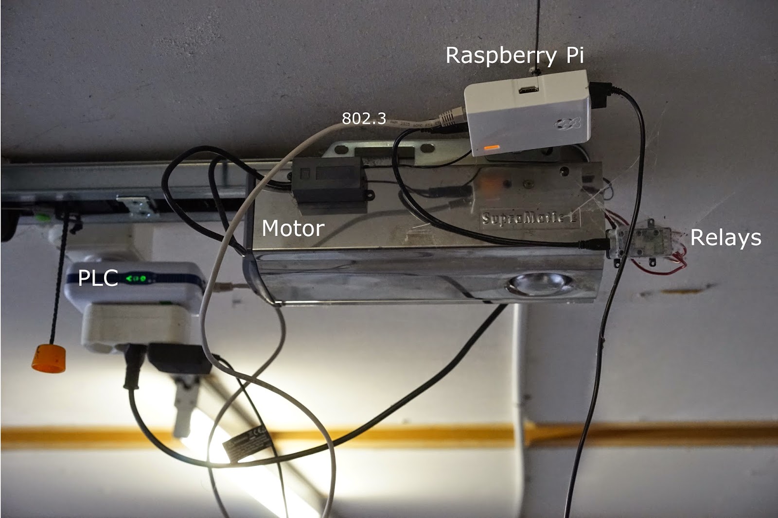
Let's take a look at the installation in my garage:


The image at the top shows the system from the side. You can see a PLC adapter, the garage door motor, the Rasperry Pi, the USB relay board, and spider webs.

I don't have an Ethernet (802.3) plug in the garage (who does?) and the Wi-Fi signal is too weak there. So I  used a PLC adapter instead. I have a few of them in my house as the wireless signal has trouble crossing floors. Such an adapter transmits Ethernet packets over electrical conductors.
The electrical motor doesn't seem to be a disturbance at all.

The Raspberry Pi is simply mounted on a screw.

The image at the bottom shows the rear panel of the garage door motor.
Remember in my system it is possible to distinguish opening and closing the door. So my USB relay board features two tiny relays. They are connected using four red wires to the board at the rear of the door motor enclosure. This matches the schematic you saw earlier.
The other wires are for the push button next to the garage door and the keypad outside.

Friday, March 28, 2014

Secure IPv6 gateway / tunnel broker using OpenVPN


For several years I have been running a VPN server at home. As a computer engineer, I know how easy it is to sniff traffic and I think everybody should connect to a VPN gateway when using a public or semi-public connection such as found in hotels, airports, and so on...

Today's setup is a Raspberry Pi on Arch Linux. This however will work fine on  most Linux distributions. Instructions are given for Debian-based distributions as well.

The generation of certificates won't be explained here as this matter is explained in several other how-to's. In fact you can even choose to use simple user/passwords.

For this to work you need to have a working IPv6 connection at home. Try http://test-ipv6.com/ and check you've got a perfect 10/10 score.

2a02:3456:ef01:abcd::/64 is the prefix my ISP assigned to me.
The VPN hosts will be in the 2a02:3456:ef01:abcd:2::/80 subnet. 

On Server

  1. Install OpenVPN
    pacman -S openvpn # Arch Linux
    sudo apt-get install openvpn # Debian, Ubuntu, Raspbian...
  2. Generate the appropriate certificates.
  3. Put this in /etc/openvpn/server.conf
    # Use 443 if the default port is blocked
    port 1194
    proto tcp
    dev tun
    ca /etc/openvpn/ca.crt
    cert /etc/openvpn/server.crt
    key /etc/openvpn/server.key
    dh /etc/openvpn/dh2048.pem
    tls-auth /etc/openvpn/ta.key 0

    # IP addresses that will be assigned to VPN hosts
    # will be in the following range
    server 10.8.0.0 255.255.255.0 # IPv4
    server-ipv6 2a02:3456:ef01:abcd:2::/80 # IPv6
    # That's right, clients will have both an IPv4 and IPv6 address.

    tun-ipv6

    ifconfig-pool-persist ipp.txt

    # Tell your clients how to find your home network
    push "route-ipv6 2a02:3456:ef01:abcd::/64"
    # Redirect IPv6 traffic to your VPN tunnel
    # If you remove this line, only IPv4 will go through
    # the tunnel.
    # AGAIN! If you remove this line, only IPv4 will go through
    # the tunnel. This means if the remote LAN has IPv6 connectivity
    # it will not redirect IPv6 traffic through the tunnel,
    # rendering it mostly innefective as hosts will preferably
    # use IPv6 instead of IPv4.
    # If you are curious, 2000::/3 represents all the public
    # address space assigned by IANA.
    push "route-ipv6 2000::/3"

    # Your home network subnet. I recommend using an unusual
    # private subnet.
    # If you *have* to use 192.168.1.0/24, you should do
    # IP addresses translation (NAT) so that your home network
    # appears as something else.
    # This line may be removed if you don't want VPN hosts
    # to reach your local network. You will also need
    # additional firewall rules to enforce this as clients
    # could manually enter this route themselves.
    push "route 192.168.20.0 255.255.255.0"

    # Redirect traffic through VPN tunnel
    # This will require IP forwarding in iptables
    push "redirect-gateway def1 bypass-dhcp"


    # DNS servers. Here OpenVPN. Make sure the servers you use
    # can resolve IPv6 requests, i.e. AAAA DNS records.
    push "dhcp-option DNS 208.67.222.222"
    push "dhcp-option DNS 208.67.220.220"

    comp-lzo
    user nobody
    group nobody
    persist-key
    persist-tun
    status openvpn-status.log
    verb 3

    keepalive 10 120 # ping every 10 seconds, assume down after no answer for 120 seconds
  4. Schedule the server to launch on system boot:
    systemctl enable openvpn@server.service

    (In fact you can name your file abcde.conf, and use "abcde" instead of "server" in the previous command.)
  5. You need to forward traffic from tun0 to your IPv6 capable Ethernet home network:
     iptables -t nat -A POSTROUTING -o eth0 -j MASQUERADE
    ip6tables -t nat -A POSTROUTING -o eth0 -j MASQUERADE
  6. Persist the firewall rules:
    iptables-save > /etc/iptables/iptables.rules
    ip6tables-save > /etc/iptables/ip6tables.rules

    or if you use sudo:
    sudo iptables-save | sudo tee /etc/iptables/iptables.rules
    sudo ip6tables-save | sudo tee /etc/iptables/ip6tables.rules
  7. Make sure the files are loaded on boot:
    systemctl enable iptables ip6tables
    On Debian: echo "iptables-restore < /etc/iptables/iptables.rules" >> /etc/rc.local
    echo "ip6tables-restore < /etc/iptables/ip6tables.rules" >> /etc/rc.local
  8. Allow IP forwarding. Edit /etc/sysctl.d/40-ipv6.conf:
    net.ipv6.conf.all.use_tempaddr = 2
    net.ipv6.conf.default.use_tempaddr = 2

    net.ipv6.conf.eth0.use_tempaddr = 2

    net.ipv6.conf.all.forwarding = 1

    net.ipv6.conf.default.forwarding = 0

    net.ipv6.conf.eth0.forwarding = 0
  9. Edit /etc/sysctl.d/99-sysctl.conf:
    net.ipv4.ip_forward=1

    On Debian, steps 8-9 may need to be done in the file
    /etc/sysctl.conf
  10. Reboot
On Client(s)
  1. Download the certificates from the server.
  2. Install OpenVPN
  3. Edit the client configuration (say client.conf):
    client
    dev tun
    tun-ipv6
    proto tcp
    remote your-server.com 1194
    resolv-retry infinite
    nobind
    user nobody
    group nobody
    persist-key
    persist-tun
    ca ca.crt
    cert client.crt
    key client.key
    tls-auth ta.key 1
    comp-lzo
    verb 3
  4. Run:
    sudo openvpn client.conf
  5. Ping the server:
    ping 10.8.0.1

    ping6 2a02:3456:ef01:abcd:2::1
  6. Check http://test-ipv6.com/ yields a perfect 10/10 score.

That's all folks!